Facebook
  • DMX512 decoder controller --3 Channel rgb / 4 channel rgbw
  • DMX512 decoder controller --3 Channel rgb / 4 channel rgbw
  • DMX512 decoder controller --3 Channel rgb / 4 channel rgbw
  • DMX512 decoder controller --3 Channel rgb / 4 channel rgbw
  • DMX512 decoder controller --3 Channel rgb / 4 channel rgbw
  • DMX512 decoder controller --3 Channel rgb / 4 channel rgbw
  • DMX512 decoder controller --3 Channel rgb / 4 channel rgbw
  • DMX512 decoder controller --3 Channel rgb / 4 channel rgbw
  • DMX512 decoder controller --3 Channel rgb / 4 channel rgbw
  • DMX512 decoder controller --3 Channel rgb / 4 channel rgbw
  • DMX512 decoder controller --3 Channel rgb / 4 channel rgbw
  • DMX512 decoder controller --3 Channel rgb / 4 channel rgbw
  • DMX512 decoder controller --3 Channel rgb / 4 channel rgbw
  • DMX512 decoder controller --3 Channel rgb / 4 channel rgbw
  • DMX512 decoder controller --3 Channel rgb / 4 channel rgbw
  • DMX512 decoder controller --3 Channel rgb / 4 channel rgbw
  • DMX512 decoder controller --3 Channel rgb / 4 channel rgbw
  • DMX512 decoder controller --3 Channel rgb / 4 channel rgbw
  • DMX512 decoder controller --3 Channel rgb / 4 channel rgbw
  • DMX512 decoder controller --3 Channel rgb / 4 channel rgbw
  • DMX512 decoder controller --3 Channel rgb / 4 channel rgbw
  • DMX512 decoder controller --3 Channel rgb / 4 channel rgbw

DMX512 decoder controller --3 Channel rgb / 4 channel rgbw

No.DMX-03 (RGB) / DMX-04 (RGBW)
This DMX512 decoder adopts the advanced micro control unit, It can receive the DMX-512 standard digital control signal which is internationally widely used. It changes the signal into PWM control signal to actuate the LED lamp. It can also connect the DMX digital console to change the light or each dynamic effect. In addition, when the decoder is not connected with the DMX console, it can be used as a synchronous controller. That is to say you can Synchronously control number of decoders and LED lights.

Features

  • The receiving standard DMX512 (1990) signal, and the channel value is converted to LED brightness value.
  • Three - channel occupied DMX512, through three channels to achieve color mixing effect.
  • It has two working modes, DMX mode and built-in operation mode.
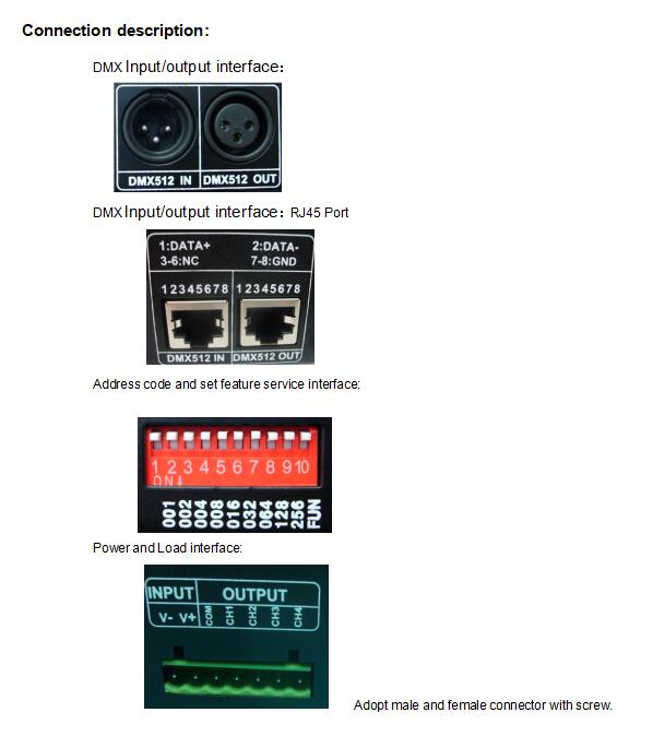
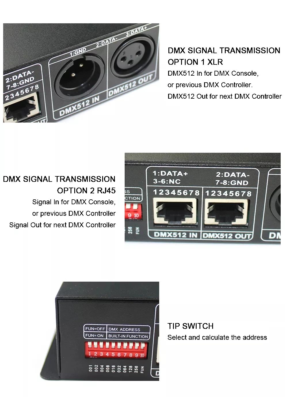
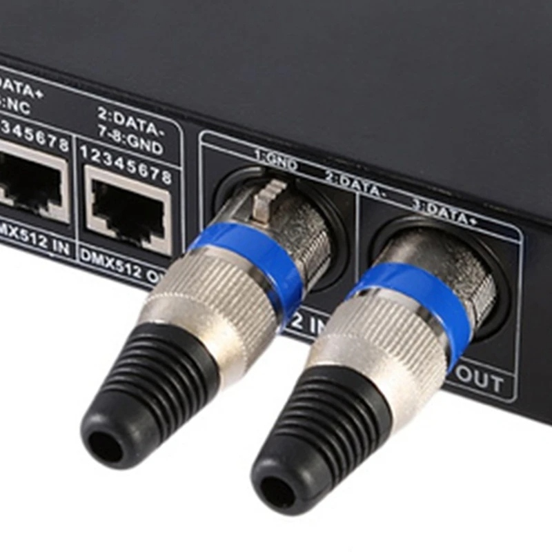
  • DMX signal interface - with two kinds of standards: XLR-3 and RJ45 interface.
  • The DMX address code can be set by dip switch.
  • It has 16 built-in modes and 32 speed grade.
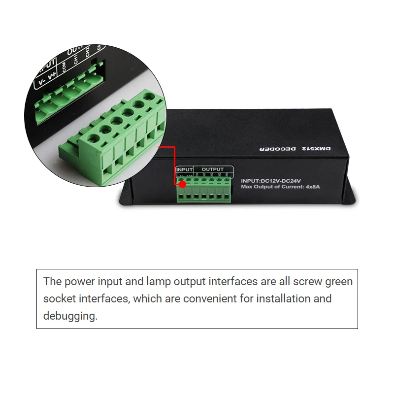
  • The output using standard green plug terminals, with mounting holes, easy to install.

  • Parameters: 
  • Input voltage: DC12~24V
  • Maximum output power: 60W 144W~ 288W
  • Dimming mode: PWM
  • Address range: 1~511
  • Operating temperature: -20-60℃
  • Protect level: IP20
  • colour: black
  • Material: plastic
Output Channel:
3 Channel --RGB
4 Channel --RGBW
Output current:
4A/CH
8A/CH
  • DMX512 decoder controller --3 Channel rgb / 4 channel rgbw
  • DMX512 decoder controller --3 Channel rgb / 4 channel rgbw
  • DMX512 decoder controller --3 Channel rgb / 4 channel rgbw
  • DMX512 decoder controller --3 Channel rgb / 4 channel rgbw
  • DMX512 decoder controller --3 Channel rgb / 4 channel rgbw
  • DMX512 decoder controller --3 Channel rgb / 4 channel rgbw
  • DMX512 decoder controller --3 Channel rgb / 4 channel rgbw
  • DMX512 decoder controller --3 Channel rgb / 4 channel rgbw
  • DMX512 decoder controller --3 Channel rgb / 4 channel rgbw
  • DMX512 decoder controller --3 Channel rgb / 4 channel rgbw
  • DMX512 decoder controller --3 Channel rgb / 4 channel rgbw
Description

Technical Parameters:                                                 

      • Working temperature: -20-60℃
      • Supply voltage: DC12~24V 
      • Output: 3 channels (RGB) / 4 channels (RGBW)
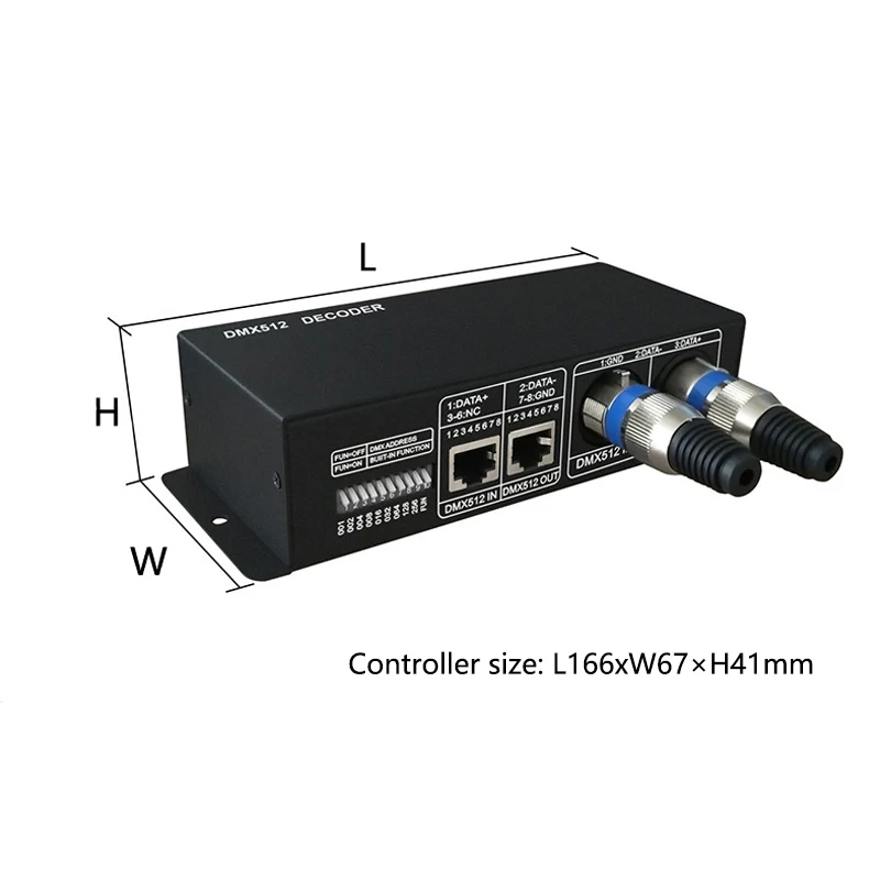
      • External dimension: L166×W67×H41mm
      • Packing size:L170×W95×H50(mm)
      • Net weight: 360g
      • Gross weight: 408g
      • Static power consumption: <1W
      • Output current: each channel 4A or 8A optional  (3 Channel)
      • Output power: 4A each channel  12V:<144W,  24V:<288W
                                       8A each channel  12V:<288W,  24V:<576W
  • Output current: each channel 4A(max 6A )  (4 Channel)
  • Output power: 12V:<192W,  24V:<384W

Controller Dimention: 

    External dimension:
    Connection description


    Direction for use

    This product is in compliance with DMX512 protocol, and compatible autoindex addressing and manual establishment address.
    Each universal DMX controller takes up 3 DMX addresses. It adopts 2 ways (auto-index addressing and code switch) to set up the address. When adopting the auto-index addressing, all switches are “off” status. When adopting the code switch to set up address, the 10th bit(FUN) is “off” status, and other 9 bits are  binary value code switch which are used to set up the DMX starting address code. The first bit is the lowest order bit, and the ninth is the highest order bit. That can set up 511 address codes. The DMX starting address code is equal to the sum of 1st to 9th bit. If move down one bit of code switch (“ON” set “1”), you can get the place-value of this bit. If move up (set “0”), the place-value is 0. For example: if you want to set up DMX starting address code for 73, you should move down the 7th, 4th, and 1st bit of code switch for “1”, and others for “0”, Then the place-value’s sum of 1st to 9th bit is 64+8+1. That is to say, the DMX512 starting address code is 73. (The correspondence dials code position is as follows)
    To choose the channel from the Dial in-line Package(DIP) Switch:

    Decimals

    1

    2

    3

    4

    5

    6

    7

    8

    9

    10

    Weight-number

    1

    2

    4

    8

    16

    32

    64

    128

    256

    FUN

     
    1. Example 1:
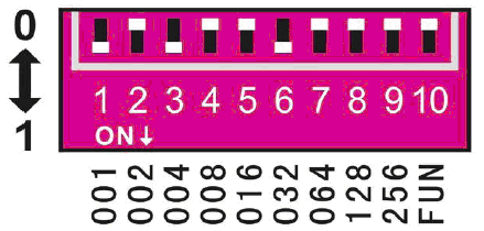
       Like figure 1, to set up the DMX starting address code for 37, should move down the 6th, 3th, 1st bit for “1”, others for “0”. Then the place-value’s sum of 1st to 9th bit is 32+4+1, as is for 37. 
    Figure 1
    1. Example 2:
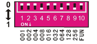
    Like figure 2, to set up the DMX starting address code for 328, should move down the 9th, 7th, 4th bit for “1”, others for “0”. Then the place-value’s sum of 1st to 9th bit is 256+64+8, as is for 328.
    Figure 2

    Typical Applications:
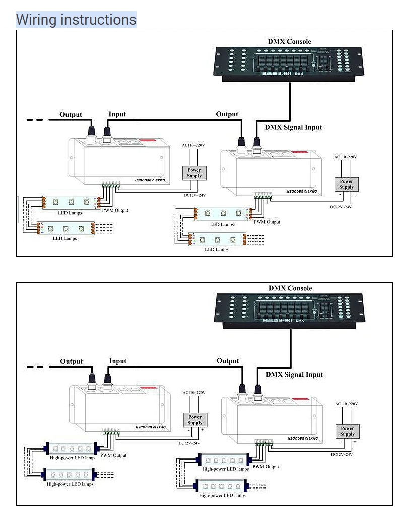

    Attention:
    1. This products Input voltage is DC12V-24V,other input voltage are not allowed. 
    2. Lead wire should be connected correctly, according to the wire color and the connecting diagram offers. 
    3. Please do not overload, the total max output current is 4A/CH or 8A/CH. 
    4. Please ensure that adequate sized cable is used from the controller to the LED lights to carry the current.
    Please also ensure that the cable is secured tightly in the connector.

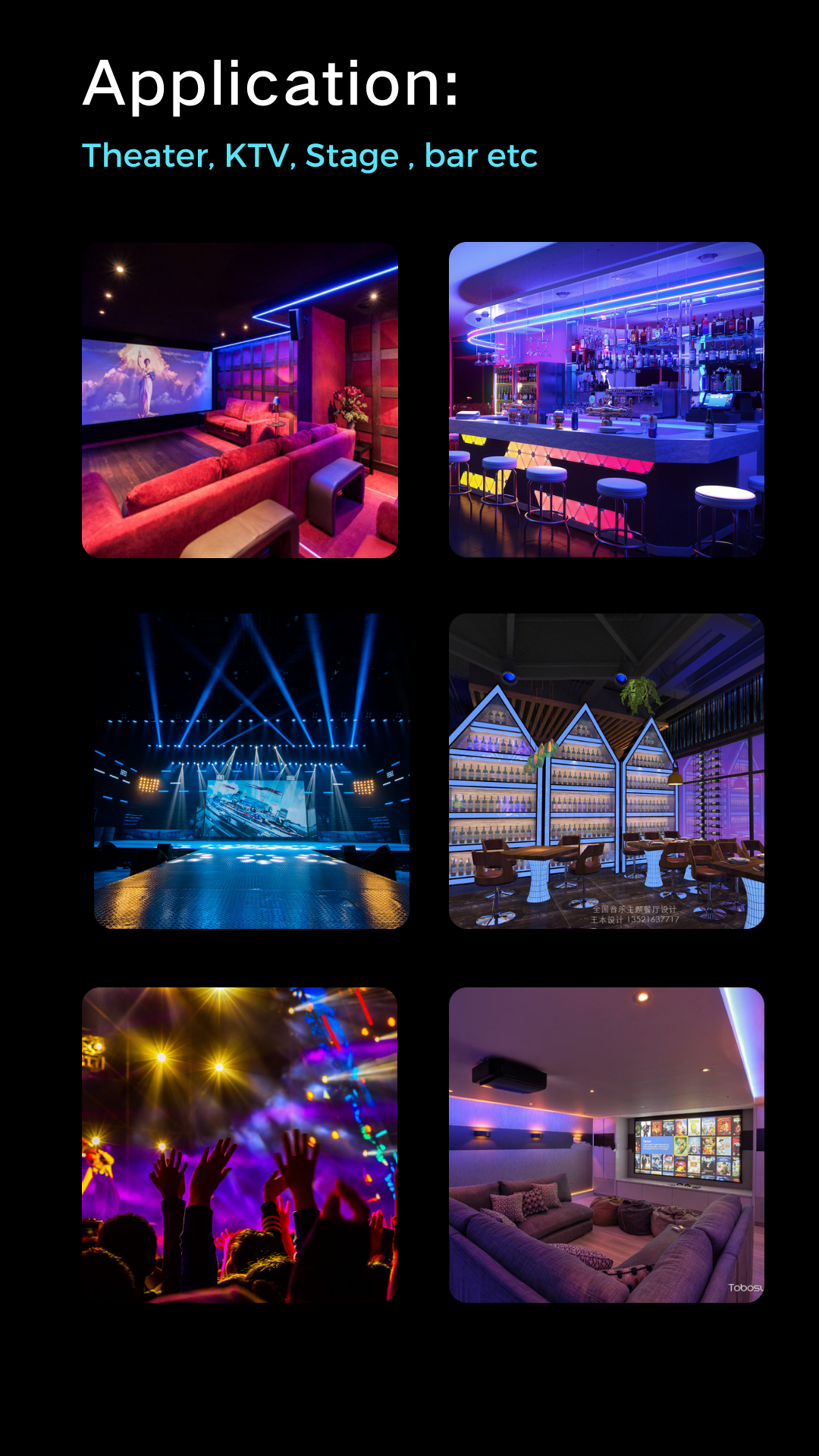
    Application: 


    Download