Technical Parameters:
- Product Name: 24 channel DMX 512 decoder with digital display
- Working temperature:-20-60℃
- Supply voltage:DC5V-24V
- Output current:3A/CH
- Output power::5V:<360W 12V:<864W, 24V:<1728W
- External dimension:249*105*43mm
- Packing size:270*130*45mm
- Net weight::720g
- Gross weight:930g
- Channel:24
- DMX512standard:DMX512/1990
- Accessory:XLR*2pcs
Connection description:
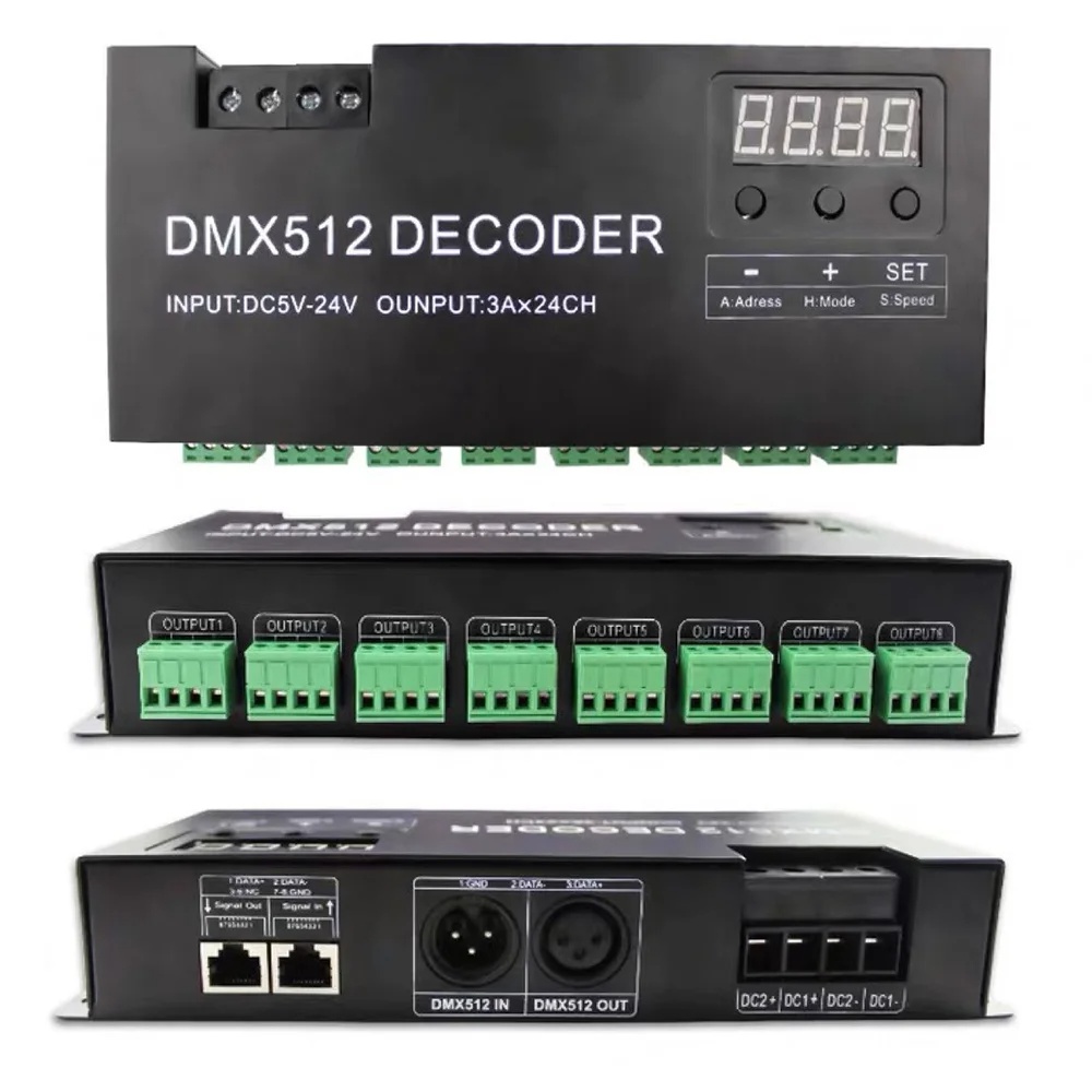
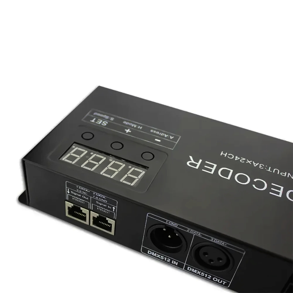
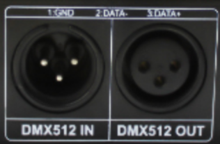
DMX Input/output interface:XLR
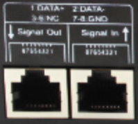
DMX Input/output interface:RJ45 Port
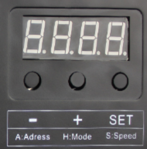
Address code and function Setting Button:
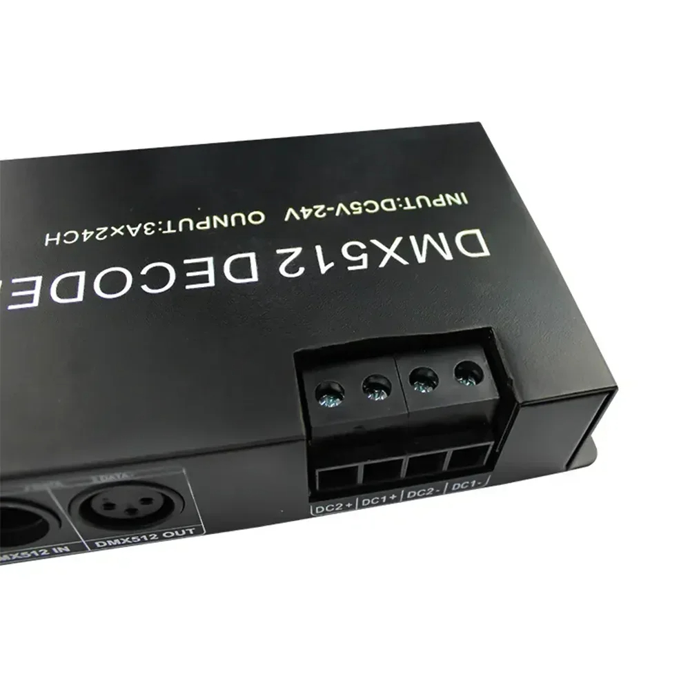
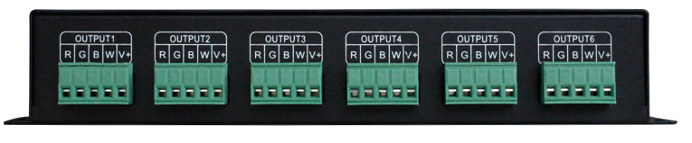
Power input and Load output interface: Used plug with screw.
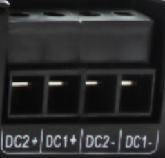
Load output:Used plug with screw.
Direction for use
1 Digital display specification:
Adopt the 4 numbers digital tube, and with three button to setting the address code.Each Decoder occupy 24 address code.The first number on the digital tube is to show the Function symbol,it have A,H,or S letter optional, and the last three number is to show the arabic date from 001-512.
1,When the fist letter shown “A”,Its on the DMX512 State,means that this decoder is under the DMX512 Signal control state, at this time connect the decoder to the DMX console with network cable, it can be controlled by the DMX console.if the digital tube shown “A001”,means that the first of the address code is 001,and the other 23 channels are Corresponding to 002,003,004……024. If connected this decoder with the other decoder,then the other decoder’s first address code is 025,and the others 23 channels of it is 026,027,028……048.It can be connected with numbers of decoder, and can be controlled alone.
If two or several decoder’s address code are the same , means that these same address code decoder are changing in the same effect, and they can be realize synchronous controlled effect.
2.When the fist letter shown “H”,it will be in the built-in mode function,means that this decoder will be working in the built-in program.the build-in models are as below:
|
Show symbols
|
Mode
|
Show symbols
|
Mode
|
|
H-00
|
Turn OFF output
|
H-05
|
Static purple
|
|
H-01
|
Static red
|
H-06
|
Static cyan
|
|
H-02
|
Static green
|
H-07
|
Static white
|
|
H-03
|
Static blue
|
H-08
|
Seven color jump(speed adjustable)
|
|
H-04
|
Static yellow
|
H-09
|
Seven color fade(speed adjustable)
|
3.When the first letter shown “S”,it will be in the built-in speed setting state function, at this state just the H-08 and the H-09 are valid,press the SET button lightly to enter the speed adjustable state,then press the button +/- can be realize the 11 level speed option. Others functions are no effective.
2、 Key function specification:
There are three buttons (Button 1: SET ,Button 2:- Button 3:+)on the decoder,the function of them are as below:
- Button SET:Mode switch key,press this key last for about 2 seconds,can be switch from function A to function H (function H to function A),press SET Button lightly can be switch from function H to function S(function S to function H)
- Button +:increase button,the last three number of the digital tube will be increase one when press the + key each time.If want to make the address code increase rapidly,just simply need to press this key last for some time.(Remarks :the max address code is 512,if it appear 512 and still press + key, it will be return back to 001) ;
- Button - :decrease button,he last three number of the digital tube will be decrease one
when press the - key each time.If want to make the address code decrease rapidly,just simply need to press this key last for some time.
Mark: After 5 seconds of no operation on the keys, the decoder enters the self-locking working state. At this time, the brightness of the digital tube is dimmed, and the three keys presses are invalid. If need to wake up the key function,then long press any key about 2s to unlock.
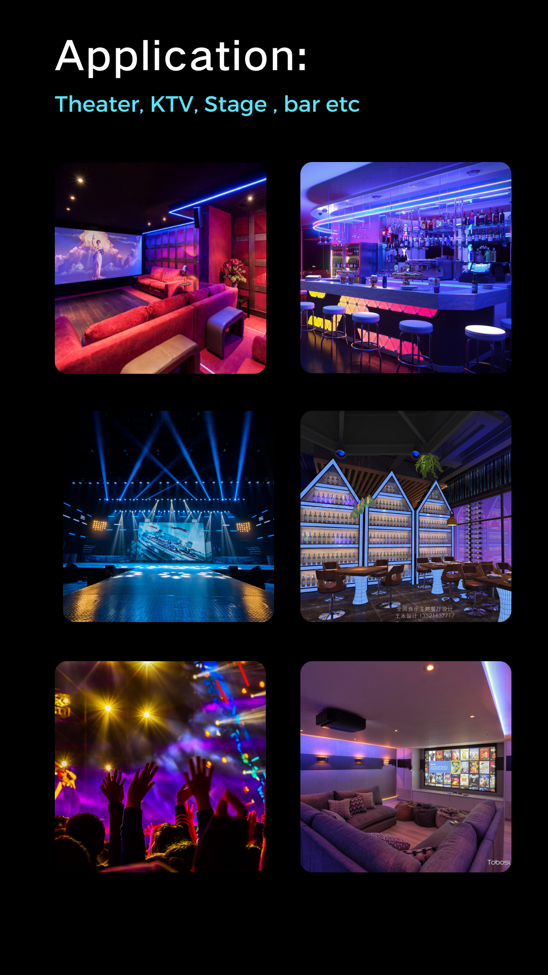
Typical Applications:
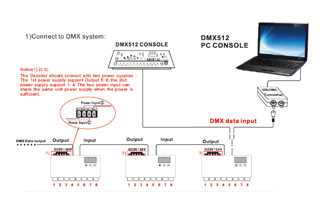
Attention:
1. This products Input voltage is DC12V-24V,other input voltage are not allowed.
2. Lead wire should be connected correctly, according to the wire color and the connecting diagram offers.
3. Please do not overload, the total max output current is 3A/CH.
4. Please ensure that adequate sized cable is used from the controller to the LED lights to carry the current.
Please also ensure that the cable is secured tightly in the connector.
Application: